Just a quick post to announce the availability of the ConvertPi on Tindie.com.
You can purchase the board for 19.90 USD by following this link.

Just a quick post to announce the availability of the ConvertPi on Tindie.com.
You can purchase the board for 19.90 USD by following this link.
Here is a quick video introduction of the ConvertPi, a fulll GPIO level translator for the Rapsberry Pi:
A quick post to share this video of my Raspberry Pi GPIO voltage converter & monitoring working with a quick Python program which blink the LEDs:
Here is a first test with webiopi, very easy tool to control the Raspberry Pi GPIOs:
Here is the first board mounted! This is a GPIO voltage translator with monitoring for the Raspberry Pi. Not tested yet but I am very happy with the quality of the PCB (made via http://smart-prototyping.com).
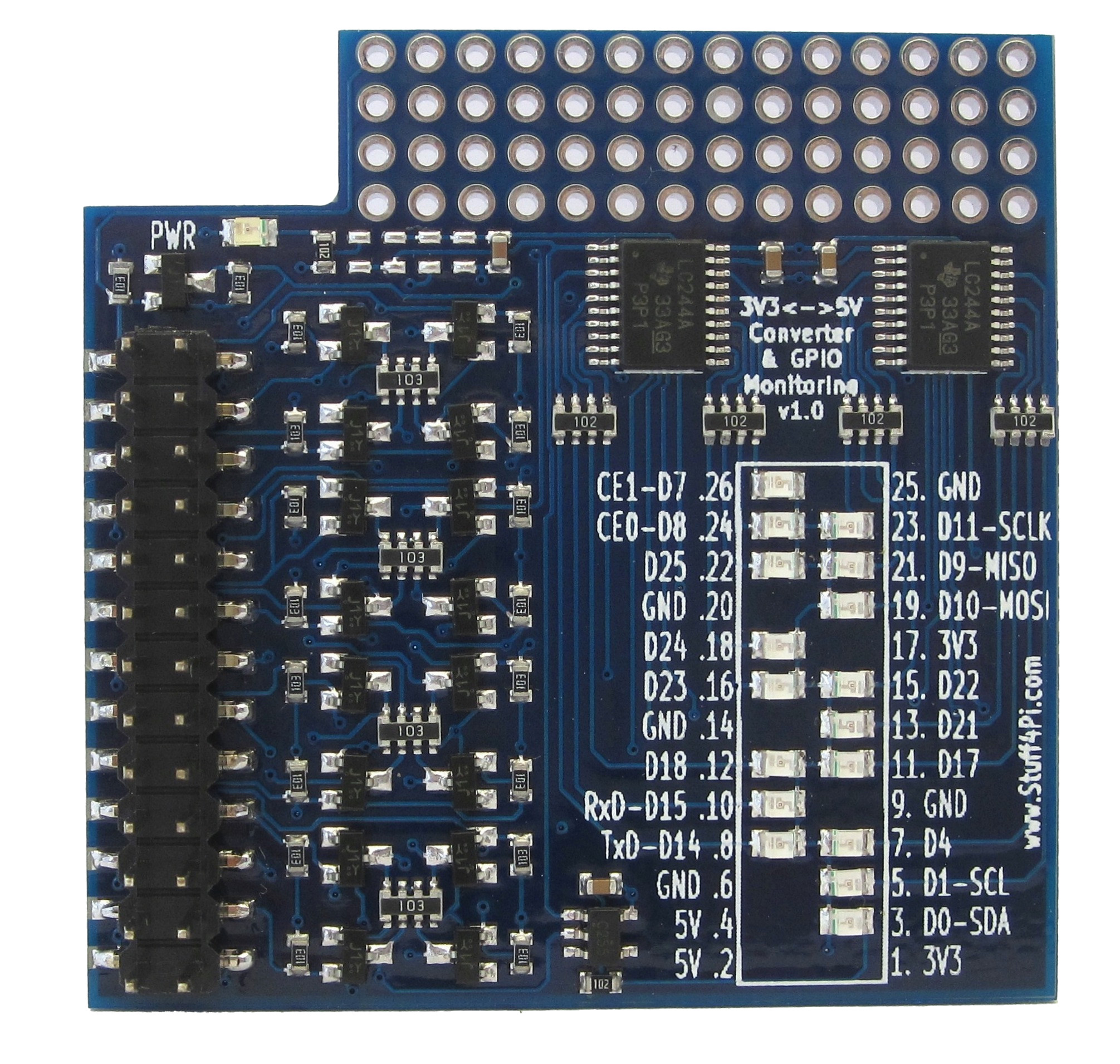
The PCB is 4 layers with 5×5 cm dimensions to fit with smart-prototypes and other PCB manufacturers offer (Seeedstudio, ITEADstudio, DFrobot, hqpcb for those living in China…).
I am going to start the debug process and verify everything is fine.
So I spent my last week end working on a full 3V3 to 5V level translator for my Raspberry Pi®. What I mean by “full” is that all the RPi GPIOs (17 lines) have their own translator. I didn’t find such a board on the market so here it is!

I am using a simple voltage translator based on an N-channel MOSFET (the BSS138) and 2 resistors. The schematic was found in this very interesting NXP application note: Bi-directional level shifter for I²C-bus and other systems.
The board is designed as a stackable, in-between, expansion board on the RPi P1 connector. All 3.3V level GPIOs are connected to the bottom connector, translated to 5V and then, available on the top connector to make it easy to stack different expansion boards.
The 5V converted GPIOs are also available on a mini prototyping area. Useful if you just need to test one IC or need to connect the GPIOs with custom connectors.
Finally, I have also added a GPIO monitoring: each pin is connected to a LED so you can monitor the status of the GPIO in real time. The LEDs are buffered so they don’t have any influence on other connections you can make with the GPIOs.
Next steps are to mount the first prototype boards and start the debugging. That will be for my next post!


